
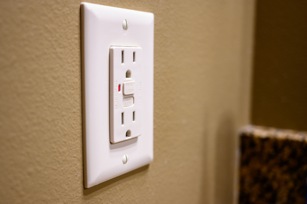
4 Easy Steps for GFCI Outlet Installations
GFCI Outlet Installation - Install GFCI by following this 4-step GFCI outlet installation guide
I didn’t prepare this GFCI outlet installation guide in 4 easy steps for conditions where everything is perfect and nothing can go wrong. That’s why it is a little longer than others.
GFCI – (Ground Fault Circuit Interrupter)
So don’t start installing GFCI without reading description of items 1-4, it’s extremely important for your safety. Good luck on your GFCI outlet installation project!
1. Disconnect power supply to the electrical outlet you are planning to remove and install GFCI receptacle in its place. The safest method is to turn off the main breaker in the electrical panel or remove the main fuse
2. Remove wires from an old electrical outlet
3. Correctly install wires on the new GFCI receptacle terminals
4. Secure the new GFCI receptacle in place, install GFCI receptacle cover plate and test installation
Easy, isn’t it… and safe if you follow the steps below.

 The minimum required tools for this 4 step GFCI outlet installation are:


- The table lamp – for testing (or some other devices like those on my picture)
- The screwdriver (flat and Philips recommended)
- Electrical tape – to insulate GFCI receptacle terminals
- Electrical pliers and wire strippers – this might not be necessary, but in some cases it will make this GFCI installation much easier
- Wire nuts and 6″ of #14 or #12 copper wire – if some slightly more advanced testing or installation is necessary
#1. This is the most important part of the GFCI outlet installation process – you have to make sure that the wires you’re installing receptacle on HAVE NO POWER!
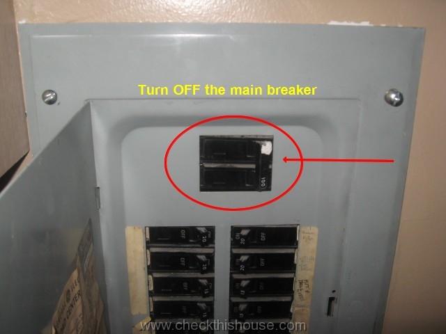 The best way would be to turn off the main breaker or pull out the main fuse in the electrical panel. By doing this you wouldn’t have to worry about testing and figuring out unmarked circuits. If you have plenty of daylight or a good flashlight / another source of light for this project – this is the safest, easiest, and the fastest way to go before attempting to install GFCI.
Before turning off the breakers or removing fuses and starting GFCI outlet installation – manually turn off electronic devices (computers, video game consoles, etc.) – they might be sensitive to an abrupt power loss. Also, if you have a burglar alarm or any other device that requires constant power supply or it will otherwise notify your provider, make a phone call and let them know that your power will be out for a few minutes (that is how long it usually takes to install a GFCI receptacle).
Even if your electrical panel has a fuse or circuit breaker, pointing (labeled) directly to the spot that the new GFCI outlet installation is going to take place, check that circuit with some type of a testing device or a table lamp after the breaker (or fuse) have been turned off / removed.
There are a few reasons for this double-checking before beginning GFCI outlet installation:
 Since the time of electrical panel original installation or labeling, there could be some changes / remodeling performed, and description inside the panel is no longer pointing out to the same spot. By turning the breaker off or removing the fuse, you might be disconnecting power from something other than the outlet you’re assuming it is protected by this fuse / breaker. Double check it, triple check it, because installing GFCI outlet on hot wires might hurt or even kill you.
 Always test for power in both sockets of your existing outlet. There might be a separate power supply for each side of your receptacle. Small tabs between the wire terminals on both sides of the receptacle are sometimes removed and two separate sets of wires from two breakers / fuses connected on each side.
You cannot perform GFCI outlet installation in such configuration – don’t even try! You have either to eliminate one of the circuits or install two separate GFCI receptacles – get a licensed electrician for that.
If your testing device plugged into the power outlet shows no activity with the breaker / fuse in either “on” or “off” position there might be a broken wire at the receptacle terminal, faulty outlet itself or many other reasons. In such case, to make sure that there’s no power in the wiring supplying this receptacle (since you can’t test it without removing it from the box), I would advise you to turn of the main breaker / pull the main fuse or call an electrician (if you have previously decided otherwise).
After you’re 100% sure that the power is OFF, GFCI outlet installation itself becomes quick and easy… almost always.
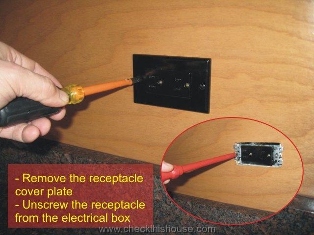
#2. GFCI outlet installation – removing wires from an old outlet
- Unscrew the outlet cover plate
- Unscrew the receptacle and carefully pull it out from the box
 Because electrical box plate edges might be sharp and damage the wire insulation (while you pulling it out) this is extremely important when dealing with old, cloth & rubber-insulated wiring. This old insulation will sometimes disintegrate while you’re working on your outlet – if you notice cracks / gaps in insulating material, call the electrician, don’t force those bare wires back into the box!
Also, if instead of a copper you’ll notice an aluminum wire connected to the electrical outlet… it’s a whole different story, call a qualified electrician / don’t install GFCI receptacle on an aluminum wire – it’s a safety hazard, and such installations are not permitted.
GFCI outlet installation – 2 wires inside the box
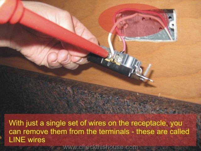 If you only have 2 wires (not counting the ground wire – green, bare or other color marked with a green tape / connected to the green screw) attached to the receptacle (one should be white or light gray plus a second color), those are called LINE wires.
Remove both of them from the receptacle and proceed to the next #3 step of the GFCI outlet installation.
GFCI outlet installation – 3 wires inside the box
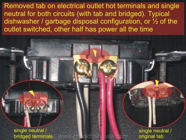 If you have 3 wires – white and two color (plus ground), and open tab(s) between the receptacle hot terminals (between color wires), there’s either 2 separate circuits (explained earlier), or half of the outlet may be controlled by the switch. You can eliminate switching by capping the switch leg (color wire from the switch) with a wire nut (make it tight and use some electrical tape so it doesn’t fall off the wire) or cap the other wire if you need to have a GFCI controlled by the switch.
GFCI outlet installation – 4 wires inside the box
 If you have 4 wires (plus ground), and closed tabs between the receptacle terminals, one pair of wires is a LINE (main power supply) and second is called LOAD (feeds power to other receptacle).
To determine which one is LOAD and LINE – you must know this to properly install GFCI receptacle (use this also to identify switched / constant power wires location) – follow those steps:


 Remove one set of wires from the receptacle terminals – one white and one color wire coming out of the single conduit or cable inside the electrical box – this is very important / don’t use white and color from different cables / conduits!
- Place wire nuts on each of the removed wires
- Carefully push the wires back into the electrical box
- Re-install the receptacle / cover plate
- Turn ON the power at the electrical panel
- Using your favorite tester check if there’s power at the receptacle
If there’s no power – capped / disconnected wires are the LINE and two wires still attached to the receptacle are the LOAD
To determine switched and hot wire (one white and two color wires connected to the outlet / tab broken between color wires), perform the same test as above except for removing white wire from the outlet terminal. If you can toggle the lamp ON/OFF with a wall switch, your single, disconnected and capped wire inside the box has a constant power ON.
Turn the power back OFF at the service panel, carefully remove the receptacle from the electrical box, mark pairs of wires LOAD & LINE, or LINE & SWITCH LEG and remove the remaining wires from the receptacle.
#3. GFCI outlet installation – attaching wires to the new GFCI receptacle terminals

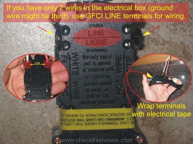 GFCI receptacle terminals are marked LINE & LOAD, with the LOAD being usually covered with a yellow tape, if you don’t need them (only two wires in the box), you can leave the tape on.
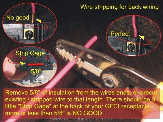
After preparing wire ends (first two pictures) secure the two LINE marked wires to the LINE marked terminals on the GFCI receptacle:
- White or light gray color wire to the GFCI receptacle white / silver terminal screw
- Color wire to the GFCI receptacle black (gold / brass) terminal screw
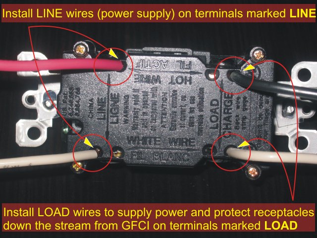 Secure LOAD marked wires to the LOAD marked GFCI receptacle terminal.
Secure ground wire (if you have one, or if your local code requires one) to the GREEN screw on the GFCI receptacle. If using any other than green color insulated wire for grounding purposes, mark both ends of the wire with green color electrical tape.

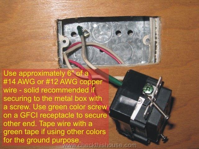 EMT pipe (electrical metal conduit) – some jurisdictions require extra ground wire between the receptacle and a metal box, or receptacle – box – electrical panel.
NM cable (nonmetallic sheathed cable) – the most common residential wiring today (not really in Illinois) – if used with a metal box, bare ground wire bonded to the box terminal and / or directly to the GFCI receptacle ground screw (the only option for plastic boxes).
AC Cable known as BX – it has an aluminum bond wire – don’t use it as a GFCI receptacle ground
Remember, if your house electrical wiring system has no ground, properly installed GFCI receptacle WILL PROTECT YOU from electrical shock, but it will not provide grounding path for the connected equipment.
Find out more about NEC Requirement for GFCI Without Ground Installation.
While performing GFCI outlet installation use electrical tape to cover installed GFCI receptacle wire terminals. This will help to prevent any loose wire from snapping off the device (even partially) and touching electrical box (common for stranded wires if improperly installed – see pictures under #3 section). Electrical tape is also to protect anyone who would forget to turn OFF the power before attempting to service GFCI receptacle.
#4. GFCI outlet installation – securing GFCI receptacle in place and testing
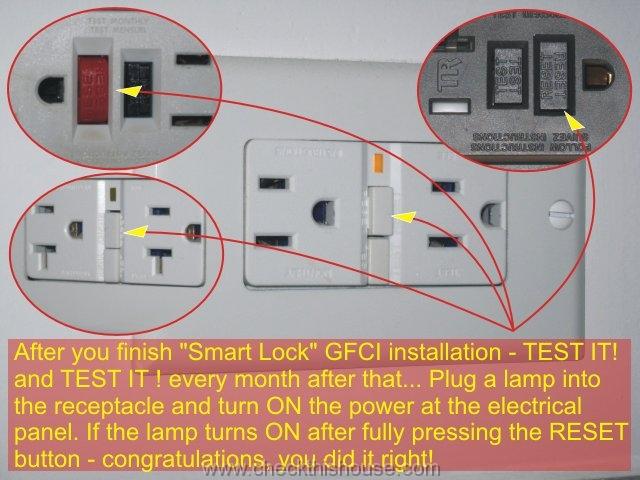
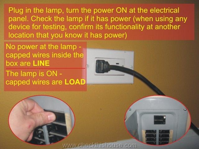
 Carefully fold the installed wires behind the GFCI outlet and push it back into the electrical box, secure the receptacle with screws and re-install cover plate. Use your favorite testing device / lamp for this next step. Plug the lamp into the GFCI receptacle and turn ON the power at the main electrical panel.
Smart Lock type GFCI receptacles are shipped in a tripped / OFF position, so the lamp should be OFF until you fully depress RESET button. If nothing happens when you do that, LOAD & LINE wires on the newly installed GFCI receptacle have been most likely switched, or you have a faulty device – DISCONNECT the power and check the installation.

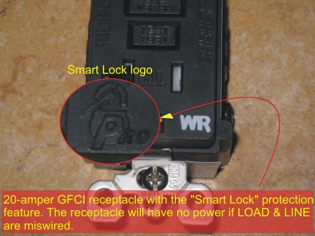 With the newly installed GFCI receptacles showing the “Smart Lock” sign, miswiring will simply prevent it from operating / there will be no power in the GFCI receptacle sockets and for the outlets connected to it down the stream.
However, older GFCI receptacles without the “Smart Lock” feature will still have power after tripping if LOAD & LINE wires have been switched. Unfortunately, there’s still millions of those devices installed in our homes, so take your table lamp and TEST IT! Or get a GFCI tester for under ten dollars, and use it every month.
You might be in a situation where installing GFCI outlet is not be possible due to an overfilled (too many wires) or undersized / shallow electrical box – GFCI receptacle is 1.5 to 2 times larger (deeper) than a regular outlet and some electrical boxes won’t be able to accommodate it. One of the possible solutions in such case is to install a GFCI breaker that will protect entire circuit.
Important things to remember – GFCI outlet installation in a place of the existing electrical outlet should be performed by following your current local jurisdiction requirements – this might not be entirely the latest NEC (National Electrical Code) but should be very close to it – find out required GFCI locations based on 2008 NEC.
Some of the GFCI outlet installation location examples would be a kitchen GFCI, bathroom GFCI, and a laundry GFCI. If you remove a regular electrical outlet from either of those locations in order to replace it with a GFCI receptacle, this new device should be
- 20-ampere rated
- installed on a #12 AWG wire
- protected by a 20-ampere rated breaker / fuse
In many cases, this would require spending a few hundred $$$ (for the electrician). However, if your plan was to replace those wires anyway, do it right – shortcuts sometimes cause fire.
GFCI maintenance – extremely important and easy to follow procedures.
Comments are closed.